I’ve been developing a FreeCAD macro for a while which uses the PartDesign workbench: https://github.com/vectronic/freecad-legify-macros
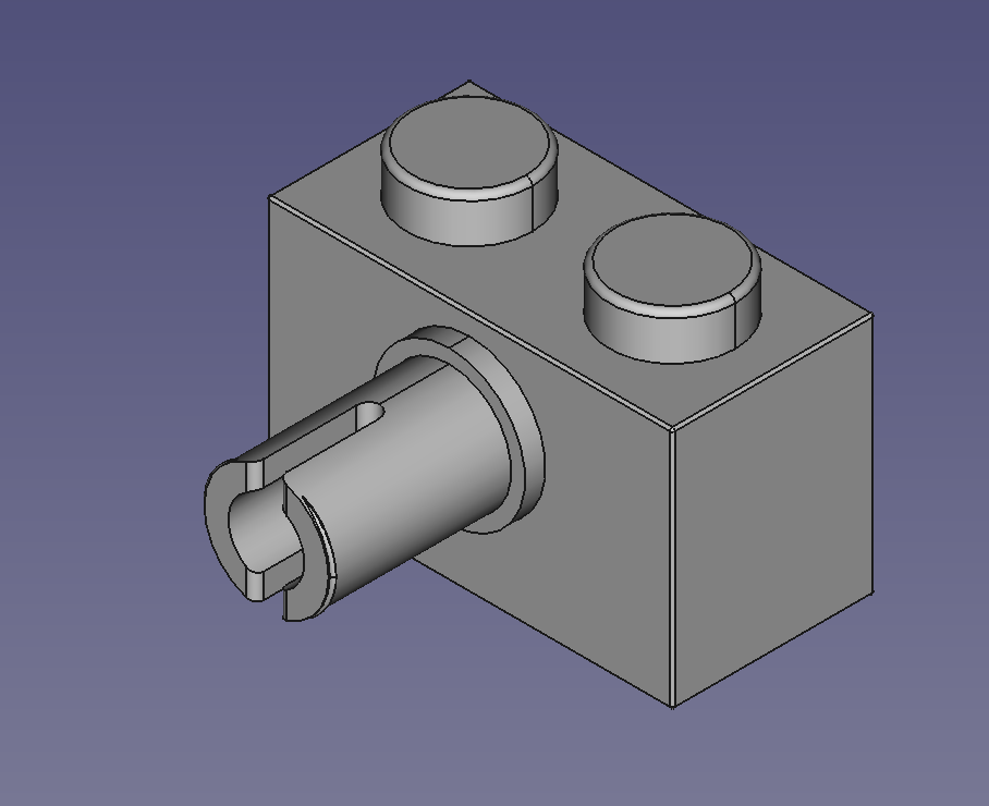
I’m just wrapping up support for rendering technic pins (work in progress screenshot below) and this effort has led me to a few more nuggets of information relating to PartDesign and Python scripting in FreeCAD.
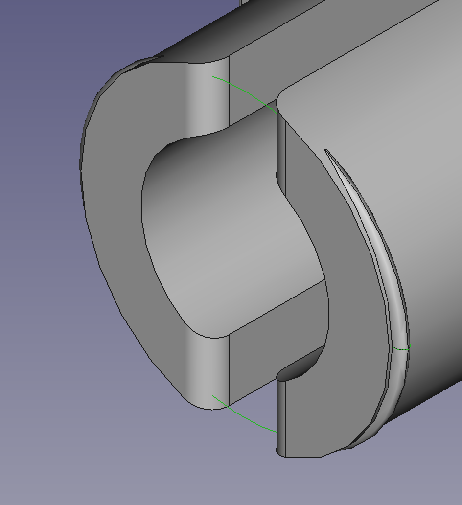
Additive Pipe With Path and Profile Sketches
Developing the flange on the pin seen below introduced me to AdditivePipe and the fact that two sketches were required for a single feature.
Sample code snippet:
pin_pipe_path_sketch = body.newObject("Sketcher::SketchObject","pin_pipe_path_sketch")
pin_pipe_path_sketch.Support = (flange_path_sketch_plane, '')
pin_pipe_path_sketch.MapMode = 'FlatFace'

pin_pipe_profile_sketch = body.newObject("Sketcher::SketchObject", "pin_pipe_profile_sketch")
pin_pipe_profile_sketch.Support = [(pin_pipe_path_sketch, 'Edge1')]
pin_pipe_profile_sketch.MapMode = 'ObjectXZ'

pin_pipe = body.newObject("PartDesign::AdditivePipe", "pin_pipe")
pin_pipe.Profile = pin_pipe_profile_sketch
pin_pipe.Spine = pin_pipe_path_sketch
As seen in the code snippet above, I also needed to use a new MapMode. I had previously been using MapMode = 'FlatFace' by default everywhere.
Now I have a new level of understanding on just what MapMode means…
Sketch Placement and Rotation
When the same feature was needed on different sides of the brick (e.g. a stud on the front side and on the left side of a brick) I had been relying on the fact that I was creating sketches programmatically.
In other words, a sketch for the front side stud would be created with different parts and constraints to that for the left side stud e.g. a horizontal LineSegment in place of a vertical LineSegment.
However, this approach fell apart for the notch sketch as I was struggling to get the constraint solver to work for each of the four different directions in which these sketches needed to be created. I nearly ended up writing four completely separate chunks of code to create the same sketch shape: one for each direction.
Clearly a better approach was needed, and obviously, FreeCAD provides one!
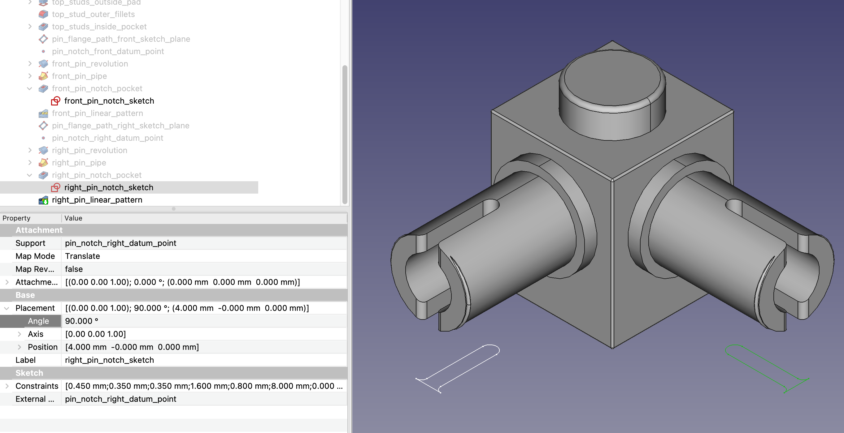
The new, better and correct approach is to create the same sketch for all four directions, but to rotate the Placement of the sketch depending on the direction.
Sample code snippet:
label = "right"
rotation = 270
pin_notch_sketch = body.newObject("Sketcher::SketchObject", label + "_pin_notch_sketch")
pin_notch_sketch.Support = [(datum_point, '')]
pin_notch_sketch.MapMode = 'Translate'
pin_notch_sketch.Placement = Placement(Vector(0, 0, 0), Rotation(Vector(0, 0, 1), rotation))
An example of two sketches, created by the same code, but rotated differently:
Body.Tip Gotcha
And finally, a ’tip’ about Body.Tip.
On most features, the following code will update the Body.Tip to the new feature:
pin_pipe = body.newObject("PartDesign::AdditivePipe", "pin_pipe")
However, for some reason (unknown to me), this will not update the Body.Tip when adding particular features such as a LinearPattern or Mirrored.
Instead, the following WILL update the Body.Tip:
pin_linear_pattern = doc.addObject("PartDesign::LinearPattern", "pin_linear_pattern")
body.addObject(pin_linear_pattern)
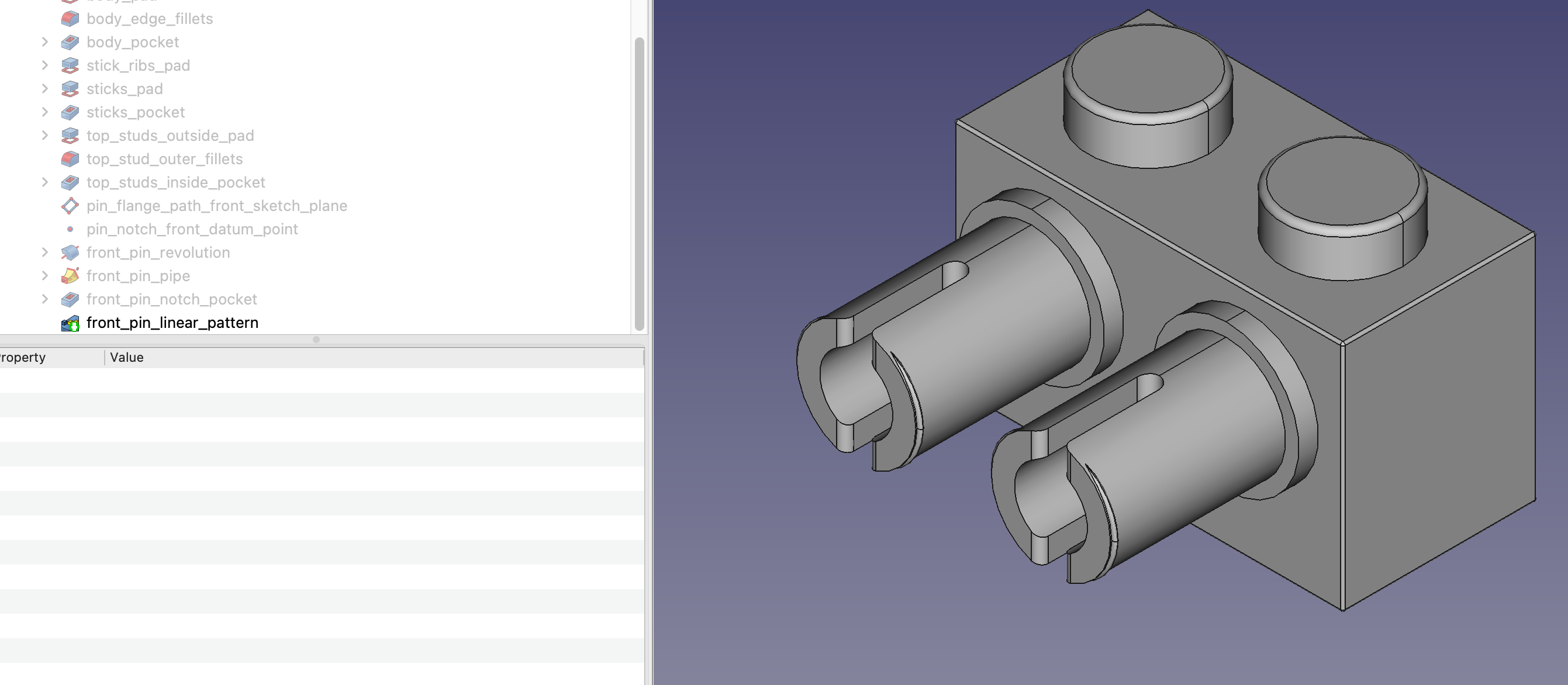
A successfully applied LinearPattern with the Body.Tip updated: